Search This Blog

Sunday, December 31, 2023

Dell Vostro 347017530-1i3-8th Gen Desktop no display


 Orange Light Blinking
Check all Coil Impadance is Ok
Check all Voltages Supply
On PL5001 Ram voltage is Not Present
Check PU5001 Ram ic
RT8231A
VDD 5v
Vtt 0.6v also come
S3 and S5 also Ok
But PowerGood Pin 10 and TON pin 9 is Not Coming
Then check R4802 PWR_VDDQ_PG One Side 3v Another side 0v Its 47k also on PR5009 PWR_VDDQ_VIN
One Side 12v another Side 0v its showing 620k same as Schematic
Replace Both Resistors R4802 replace 47k and PR5009  Replace 200k 
Now PR5009 PWR_VDDQ_VIN is12v Another side PWR_VDDQ_TON is 1v
And R4802 PWR_VDDQ_PG Both Side 3v is coming and White light glow and Display also Come

Monday, December 4, 2023

 How to enable the old context menu in Windows 11

1. Open Windows Terminal (Admin)

On your Win 11 OS, right-click on the Start button and select “Windows Terminal (Admin)” from the pop-up menu.


2. Enable Windows 11 old context menu
Now, on your Windows terminal, paste the below-given command and hit the Enter key. This will edit some value in the OS registry to get back the old context menu like Windows 10.
3. Restart File Explorer Service
To apply the changes we have done using the above command, we need to restart the Explorer service on your Win 11. For that, we can either use Task Manager or Windows terminal (which already opened).

Using Windows Terminal (Admin)

First Run:

Then type the next command to start the Windows explorer service again. In case, you want to switch between apps before starting the explorer service, use  – Alt+Tab keys
reg.exe add “HKCU\Software\Classes\CLSID\{86ca1aa0-34aa-4e8b-a509-50c905bae2a2}\InprocServer32” /ftaskkill /f /IM explorer.exe
taskkill /f /IM explorer.exe
start explorer.exe

Saturday, November 4, 2023

How to bypass internet connection to install Windows 11

  1. Select your region setting after the installation on the first page of the out-of-the-box experience (OOBE).

    Windows 11 OOBE region

  2. Click the Yes button.

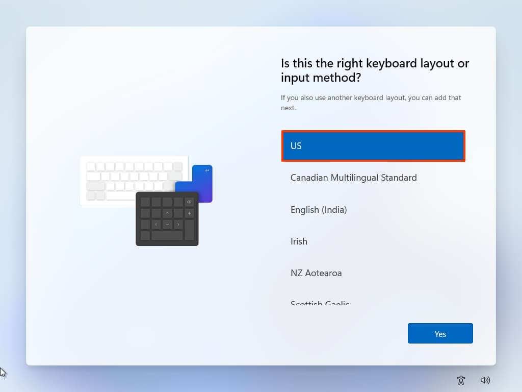
  3. Select your keyboard layout setting.

    Keyboard layout

  4. Click the Yes button.

  5. Click the Skip button if you do not need to configure a second layout.

  6. On the “Oops, you’ve lost internet connection” or “Let’s connect you to a network” page, use the “Shift + F10” keyboard shortcut.

  7. In Command Prompt, type the OOBE\BYPASSNRO command to bypass network requirements on Windows 11 and press Enter.
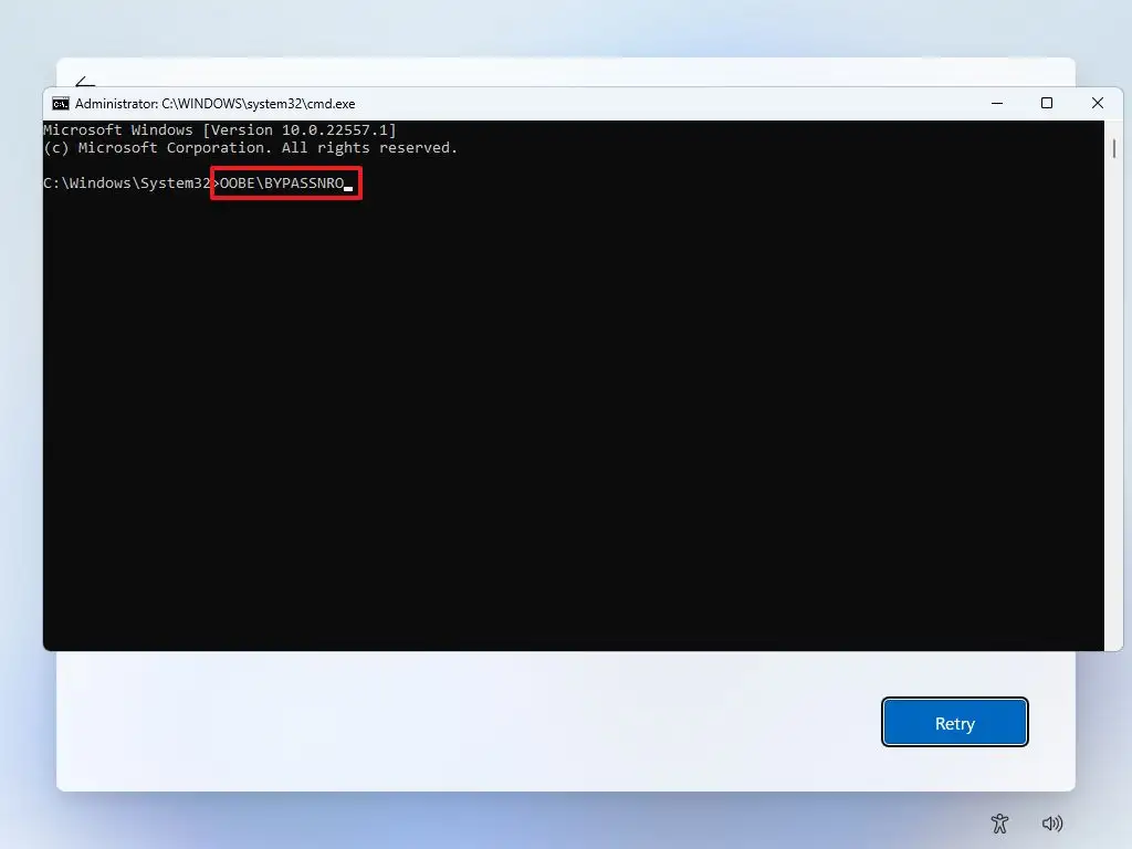
    Oobe bypassnro command

  8. The computer will restart automatically, and the out-of-box experience (OOBE) will start again.

    Quick note: You will need to select the region and keyboard settings again to get to the network connection page.
  9. Click the “I don’t have internet” option.
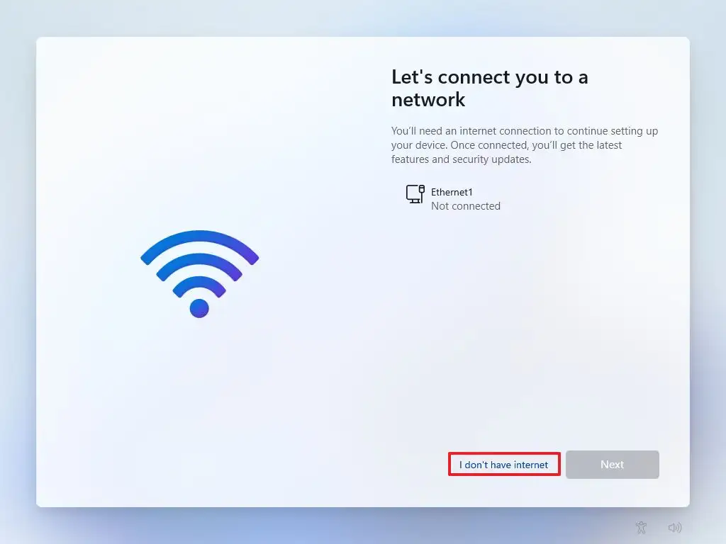
    Windows 11 OOBE don't have internet

    1. Click the “Continue with limited setup” option.
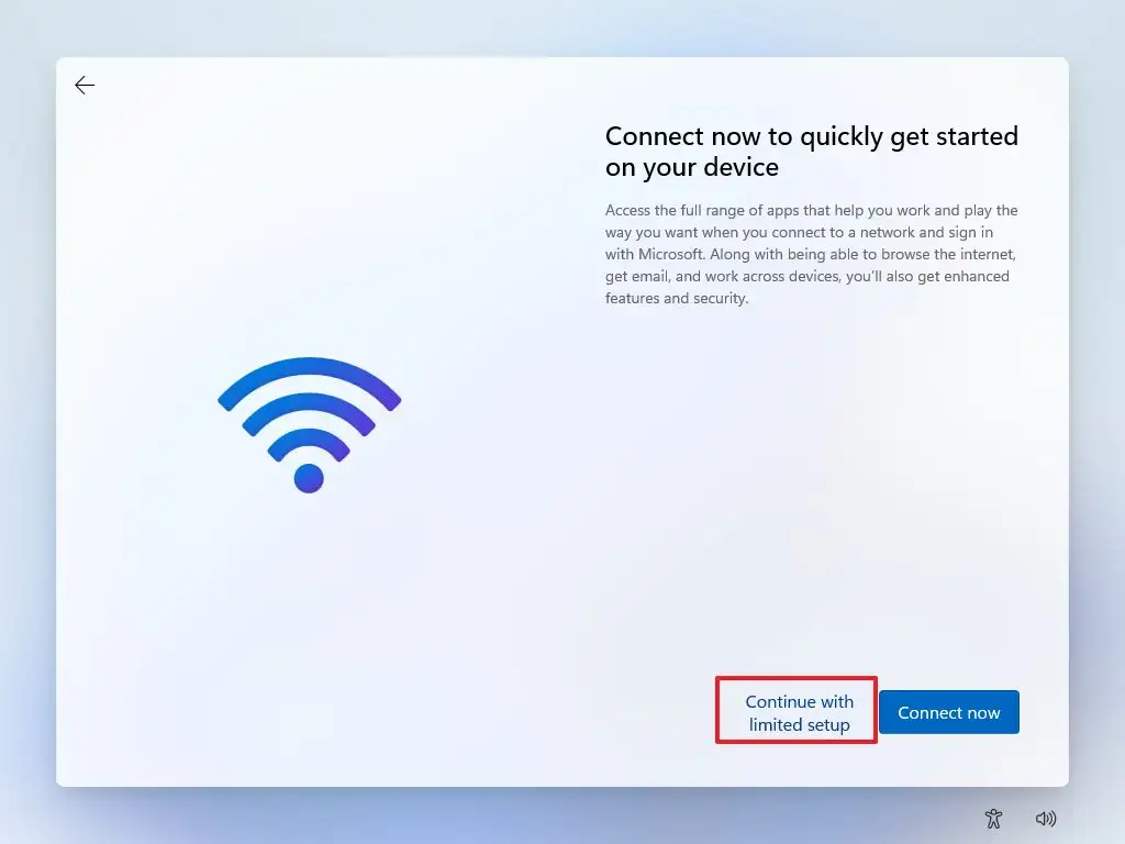
      Continue with limited setup

    2. Click the Accept button (if applicable).

    3. Confirm the name of the local default account on Windows 11.
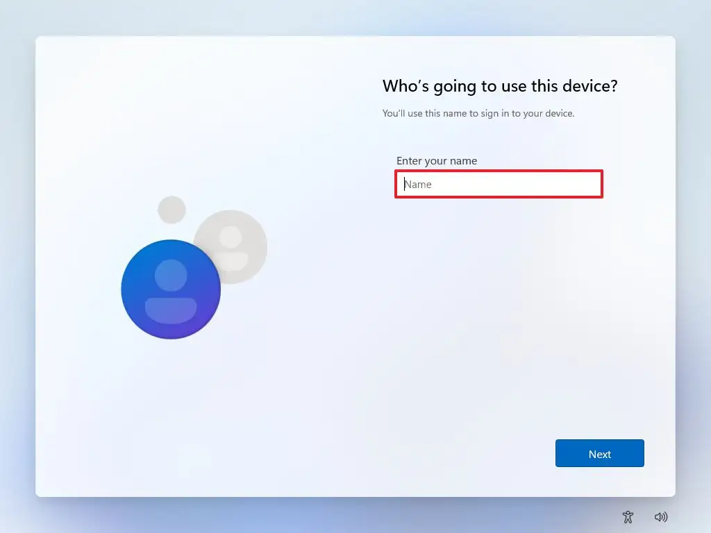
      Create local account

    4. Click the Next button.

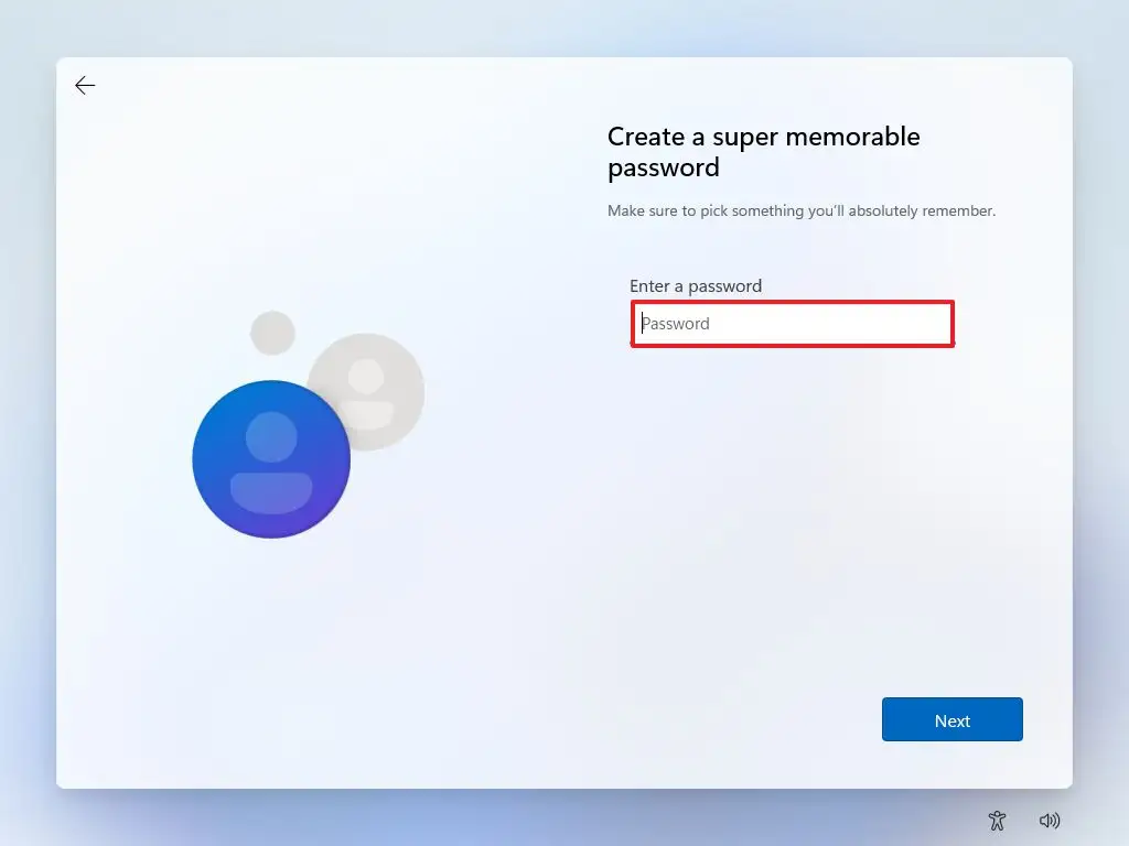
    5. Create a password for the account.

      Create local account password

    6. Click the Next button.

    7. Confirm the account password.

    8. Click the Next button.

    9. Select and complete the three security questions to recover the account.
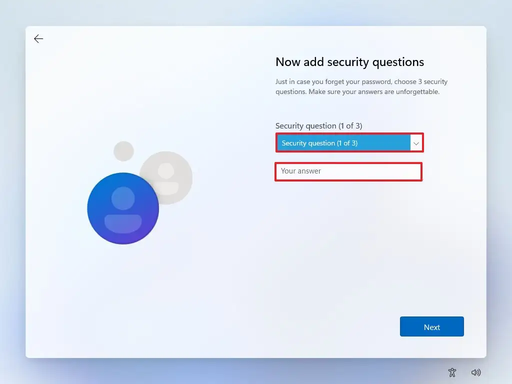
      Configure local account security questions

    10. Click the Next button.

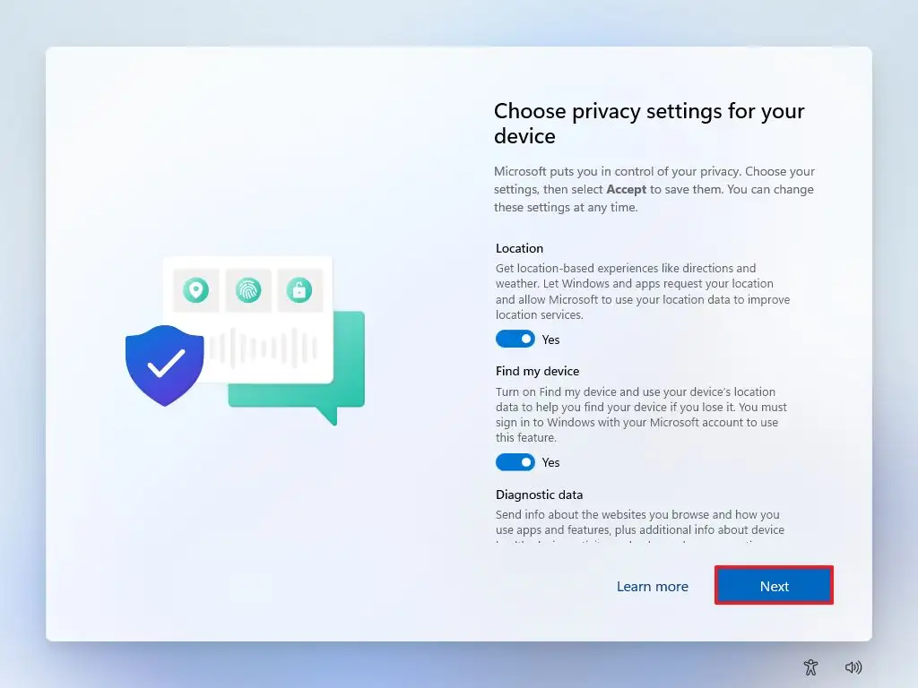
    11. Choose the privacy settings.

      Windows 11 OOBE privacy settings

    12. Click the Next button.

    13. Click the Next button again.

    14. Click the Accept button.

Friday, November 3, 2023

Doctor Computer & Chiplevel

Doctor Computer & Chiplevel
096330 34123

 https://www.google.com/search?client=ms-android-vivo-rvo3&sca_esv=579077719&sxsrf=AM9HkKlJ8bJoi-qCASiwFI1du6vQvDQtXw:1698998144376&q=Doctor+Computer+%26+Chiplevel&ludocid=14534383040395158716&ibp=gwp;0,7&lsig=AB86z5X9QRowlTzJ7P4ltDJaWifA&kgs=a72e7865811ec782&shndl=-1&shem=lsp&source=sh/x/loc/act/m1/2

Wednesday, November 1, 2023

LENOVO G50-45 NM-A281 ON AND OFF AFTER 10 SECONDS

DC AMP 0.019 ON STANDBY. AFTER PRESSING POWER BUTTON AMP GOES TO 0.250A AND RETURNE 0.019A.
BOARD OFF.


FIRST CHECK RTC CELL. 0.30V ON CELL. REPLACE CELL AND CHECK. BUT SAME PORBLEM.
THEN PREPARE NEW BIOS AND DO BIOS BUT SAME PROBLEM PROBLEM NOT SOLVED.
CHECK 19V CIRCUITE. ITS OK.
CHECK ALWAYS VOLTAGES 3V, 5V, 1.8V, 0.95V ALL ARE OK.
ALL IC'S POWER GOOD OK.
ALL COIL VOLTAGES ARE OK.(WHILE PRESSING POWER BUTTON & STANDBY BOTH).
ABHI KYA KAREEEEE.... THODA TECHNICALY SOCHA AND TRACE DC-DC CIRCUITE.
CHECK ALL DC-DC CIRCUITE. INPUT VOLTAGES ARE OK BUT NO OUTPUT VOLTAGES.
CHECK ALL MOSFET GATE. NOT OK. ALL GATES CONNECTED WITH SAME INPUT.
GATE ARE CONNECTED WITH +VSB. AND +VSB CONVERTER THRUE JUMPER +VSBP.
CHECK THAT JUMPER VOLTAGES. ITS SHOWING 4.80V. WHICH WAS WRONG. IT SHOUTLD BE +19V
SO BACK TRACE & FIND THE BIRTHPLACE OF +VSBP.
+VBSP BIRTHPLACE WAS ON SOT23-3 P-CH MOSFET'S DRAIN. 
MOSFET'S SOURCE 19V B+ OK BUT NO DRAIN VOLTAGE OUT.
CHECK MOSFET IN COLD MODE. GATE & DRAIN SHORT.
FIRST CONFIRM WITH JUMPER THE PR431. 
NOW PRESS POWER BUTTON. DC READING 0.530A & DISPLAY COME.

ACER E5-511G(Z5WAL LA-B211P) DEAD WITH NO DISPLAY


🔍 Physical Verification- Fresh Motherboard No Physical Damage

🪛CHECKING- RTC SECTION 
RTC SEC. OK 
BIOS write

Ram  Requirements Check all  Supply Ok The RAM_RESET (30) MISSING ?

👉 Solution - RAM POWER GOOD check  PG Resistor PullUp  One Side 1.35V opposite Side 1.23  replaced the resistor  Problem Solved 

Friday, October 27, 2023

Laptop ic equivalent

MS3UC (3.3 VOLT IC) = MS4UG, MS5GE, MS3RW, MS3WE, MS5RM, MS4LD, MS3PH, RF4EL, IR4PF
RG4QI (5.0 VOLT IC) = MT3RH, MT4DH, MT5IB, MT4XA, MT5QB
TPS51125 = TPS51125A = RT8205 = RT8205B = RT8205BGQW = UP6182 = uP6182AG ( CK=CL CJ=DA CK=CD C47 )
TPS51123 = RT8223P = UP1585QQAG (EM=EC) 20=el,20=df,20=ef eq=cg eq=dm,eq=do eq=dd=da=dc=dk DS=CC DS=CD DS=CE DS=CF DS=BJ DS=BK
TPS51285b = Code ( 3H=2E ) Dell E5450
SN0608090 = ISL6237 = PM6686 = MAX17020 = MAX8778 = TPS51427 = RT8206B ISL62366=RT8206A
TPS51116 = 5616A = RT8207 = ISL6227 = APW7108 = RT8207MZQW J7 em DH=CH DH=CA CP=DD CP=CF DH=EA CP=AJ EF=CG EF=CM EF=DG EF=DE (1.5V) RAM IC 
TPS51117 = G5603RU1U = RT8209B AO = ca AO = BM AO = CD AO = CA AO = BG = BG AO AO = CB AO = BL BH RT8209A = FH = CG CU1 FH = EE, FH = CC, DD = FH, FH =CL, FH = 8J FH = CF

TPS51216 = APW8819 (1.35V) RAM IC 
RT8207P = RT8207PGQW Code 4B=2B, 4B=2K, 4B=1L, 4B=  (1.35V) RAM IC 

RT8208XGQW FF=BK FG= FF= H8= 30= 31=
ISL88731CHRTZ=BQ24745
ISL6262 = ISL6266
6265 INTERSIL ISL6265AHRTZ
6267 INTERSIL ISL6267HRZ
ISL6268=APW7318
MAX8734A = RT8203
TPS51211 = TPS51212
isl62883 = isl62882
uP6128A = RT8202A (Marked DJ-) = G5602
BQ24728 = BQ24725A
SN10504 = SN0608098 RHBR
MAX8724E = max1908 (EF= DE) = UP6163AG (1.5V)
TPS51716 = PTS51216
P2805MF = G5933
ISL6251 = G5209
RT8204B=RT8204C=RT8204L H6=CH H6=CB H6=CG H6=BE H6=CC FR=AH FR=AM FR= J8=
ALC660=ALC883
W8769=W8763
j493 (G966-93) RT9018B (DELL VOSTRO 1015) ES = EF ES = CL = DD ES
8239 RT8239CGQW jd=de jd=ee jd=db dc=eq jd fj JD=DE JD=EE JD=DB JD JD=DC =DG
8243 RT8243AZQW 8A EE 8A EF 8A EC
9297 RT9297GQW EZ=ED EZ=EH EZ=CD
RT8015APQW_WDFN_10P el=dc 10 pin EL
RT8015BGQW / GG= GG=CE RT8015DGQW /JO=
RT8058 / CB=CC

Richtek laptop ic code

Richtek laptop ic code 
DJ= – RT8202AGQW
DJ- – RT8202APQW
DK- – RT8204PQW
JL= – RT8204AGQW
FR= – RT8204BGQW
H6= – RT8204CGQW
CJ= – RT8205AGQW
CK= – RT8205BGQW
CL= – RT8205CGQW
CB= – RT8205DGQW
DT= – RT8205EGQW
EM= – RT8205LGQW
EN= – RT8205MGQW
CP= – RT8207GQW
DH= – RT8207AGQW
EF= – RT8207LGQW
J7= – RT8207MGQW
DS= – RT8223BGQW
11= – RT8223NGQW
20 – RT8223PZQW
EP= – RT8223LGQW
EQ= – RT8223MGQW
FF= – RT8208AGQW
FG= – RT8208BGQW
H8= – RT8208DGQW
30= – RT8208EGQW
31= – RT8208FGQW
FH= – RT8209AGQW
A0= – RT8209BGQW
A3= – RT8209EGQW
JX= – RT8209LGQW
A8= – RT8209MGQW
K0= – RT8209NGQW
A6= – RT8209PGQW
EL= – RT8015A
DZ= – RT8113
CZ= – RT8561AGQW
D9= – RT9716AGQW
C7= – RT9293-20
DK – RT8204PQW WQFN 3×3-16
JL = – RT8204AGQW WQFN 3×3-16
FR = – RT8204BGQW WQFN 3×3-16
H6 = – RT8204CGQW WQFN 3×3-16
CJ = – RT8205AGQW
CK = – RT8205BGQW
CL = – RT8205CGQW
CB = – RT8205DGQW
DT = – RT8205EGQW
EM = – RT8205LGQW [RT8205AGQW]
EN = – RT8205MGQW [RT8205CGQW]
CP = – RT8207GQW
DH = – RT8207AGQW
EF = – RT8207LGQW
J7 = – RT8207MGQW
DS = – RT8223BGQW LDO Output: 70mA
11 = – RT8223NGQW LDO Output: 100mA [RT8223BGQW]
20 = – RT8223PZQW LDO Output: 100mA [RT8223BGQW]
EP = – RT8223LGQW LDO Output: 100mA [RT8223AGQW]
EQ = – RT8223MGQW LDO Output: 100mA [RT8223BGQW]
FF = – RT8208AGQW
FG = – RT8208BGQW
H8 = – RT8208DGQW
30 = – RT8208EGQW
31 = – RT8208FGQW
FH = – RT8209AGQW WQFN-16L 3×3
A0 = – RT8209BGQW WQFN-14L 3.5×3.5
A3 = – RT8209EGQW WQFN-14L 3.5×3.5
JX = – RT8209LGQW WQFN-16L 3×3
A8 = – RT8209MGQW WQFN-14L 3.5×3.5
K0 = – RT8209NGQW
A6 = – RT8209PGQW
EL = – RT8015A
DZ = – RT8113
CZ = – RT8561AGQW
D9 = – RT9716AGQW
C7 = – RT9293-20

Sunday, October 15, 2023

DELL N5010 power on but no display

Put DC supply amp.  144 - 160 ( means core not generate)


Open this laptop 

Check my basic points 


Check all coil impidence 🆗

 Check all coil voltages


   Vin section 👍✅


    3v, 5v  coil voltage 🆗


Ram voltage 👌


    3v , 5v conversion ✅


  1.8 v 👍


   Check 1.05 v pch coil (❌) not generate 


Open schamatic and trace 


1.05 v ic requirment check


    Power -5v ✅

  Enable- missing 


      This board design by wistron 


  I know,

              1.05v enble signal coming 

    Ram supply power good + 1.8v section power good 

     After mixed both power good

Known as ,

                     RUN POWER OK


RUN POWER OK  supply goes 1.05v enable signal


I check then found ram ic power good not generate


 👉 I see this path 3.3v pull up resistor(PR5004)


     One side voltage okk but other side no voltage 

 Checking purpose  shot this resister

   My board is on


After this, 

                 I chage  resister 0 ohm


My board is proper on & give display

Saturday, October 7, 2023

HOW TO DELL MANUFACTURE MODE DISABLE


 turning Off the Manufacturing Mode for the System Board

Your replacement system board is shipped with the manufacturing mode turned on. After thesystem board is installed, you must turn off the manufacturing mode for your system to operatecorrectly. If the manufacturing mode is enabled, the system may not boot correctly. In addition,changes to BIOS and CMOS settings will not be retained, and you will not be able to flash update the BIOS.To turn off the manufacturing mode, perform the following steps:

 Turn on or restart your system.

 Press <F2> immediately after you see the following message:

<F2> = System Setup

 From the main System Setup screen, press <Alt><F> to turn off the manufacturing mode.

 Review the various System Setup options and change them as necessary to your preferred


system configuration.

For details on the various options, see "Using the System Setup Program" in your User’s

Guide.

 Press <Esc> to exit the System Setup program.

Save the changes you have made and exit the program when prompted to do so.


As the system reboots, verify that the manufacturing mode is disabled.If the manufacturing mode is still turned on, the following message appears at the top of the screen:Manufacturing Mode is Detected If this message appears, repeat steps 1 through 5 to disable the manufacturing mode and restore the System Setup options.

Wednesday, August 16, 2023

Lenovo g580 not power on


Lenovo g580 
Prblm- not turning on
Action- 
            Open laptop board I see DCIN section CLR damage, 
                               Change CLR and trigger board display come
   But, 
        Major issue create-
                                       Battery plug in charging but % not increase 
 
Trace this prblm -
   1st mosfet completely switching 🆗
2nd mosfet switching 👌

 SDA,SCL path 👍
                          ( battery connector - ic - io)
   
 Battery sense resister ✅ 
Check voltage ,
      SDA, SCL PATH (3.3V)👌
   
Then, 
         I check resistor value
   SDA path resistor value ✅

SCL path resistor value not good🦸
  Change SCL path resistor  

 Battery fill percentage 

Prblm solved
👌👍

Samsung skela 315 petronus- bA41-01763a no display

Samsung skela 315 petronus- PA4101763a
      Prblm- no display

   ( this modal no schamatic)
Action-
            Put DC supply amp- .260
And  🔙  .009 - .010
    Some time amp -.350

      Stand multimeter and check
  Vin section also✅
3v 5v also ✅
    Ram voltage 👍
Core voltage not generate

Back trace ,
            board is 3rd genration
   Follow 3rd genration sequence
   Ram voltage 👌
    1.8v ✅
      1.05 VTT voltage 👍
  But not generate core voltage

1.5 VDDQ voltage (S3 state) convert one mosfet  s0 voltage
      
Mosfet input drain 1.5 voltage 👍
Mosfet output source .65 voltage (✖️)
               
  After check gate supply is missing
   Then,
             Remove this mosfet gate is ok
Change this mosfet
Board ON
Core voltage come & give display
   ( this board no schamatic and no board parts no. )
✅👍

Dell n5050 not power on


   Dell n5050
  Prblm - not turning on
Action-
           Put DC supply amp. -.001
    Stand multimeter and check
   Vin section ✅
     3v/5v coil voltage not generate(✖️)
     
Check IC requirment and jump PSL LOGIC
           Found 2 mosfet
          Q2706(n-channel)
           Q2702(p-channel)
       Q2702 mosfet gate is high
        So,
              Not trigger this mosfet

🔙 trace this circuit
        I found
         Q2705 (n-channel) mosfet 
   GATE voltage 👍
        But not trigger mosfet
      Then,
              Change q2705 mosfet
   
3v / 5v coil voltage ok
  Board is trigger on
    &  come display
👌 ✅

Sony mbx266Prblm no power on

 Sony mbx266
Prblm- no turning on 
    Action - 
              Put DC supply amp - .005
   After power btn amp same -.005
       Stand multimeter and check 
   Vin section ✅
   3v/5v coil NO voltage
      Check 3v 5v IC ( RT8223m) requirment_____
       Vin 🆗
        3v LDO 🆗
         5V LDO 👍
        EN pin voltage 🆗

        REF voltage noT generate 
          May be this line capicitor is faulty / IC faulty
          Changed IC ( RT8223M)
     prblm solved 
   Board trigger and ON , come display 

 ✅✅✅

Friday, August 11, 2023

lenovo b460e not power on fixed

5v 3v ok
No vcore supply 
Check MOSFET vcore section it plated type mosefet replaced 4 MOSFET and core ic
Laptop is ready and display come

Dell 3558 (la-b843p), 4th/5th genration board Prblm - on/off ( tripping issue)


Dell 3558 (la-b843p), 4th/5th genration board
 Prblm - on/off ( tripping issue)
          Open tha laptop and che ck all section voltage (check all voltages in ON condition 🔛)
 Vin 🆗
3v /5v 👍
Ram voltage 🆗
1.05v pch supply 👌
But, 
       No core voltage 
    👉 VR_ON enable signal not genrate
   
  I know, 
              4th/5th genration board VR_ON signal generate SOC (output)
      When,
                 SOC requirment full 
                                (Vccst_pwrgood)
 Then, 
           SOC release VR_ON enable signal core IC
         Check back trace 
          Vccst_pwrgd signal R707(100k) RESISTER inside voltage ok but no outside voltage 

    👉Change resister VR_ON 🆗
   but board not proper ON

   🔙 io chip requirment (NPCE 285)
     SYS_PWROK (3.3V) ✅
      ALL_SYS_PWRGD (3.3V)👍
        PCH_PWROK (NO VOLTAGE)😔
              & beep ground
       
      After all, 

    I check core IC voltage (ISL95813)
      All voltage ok
          Vr_on (1.5v)✅
          Vcc voltage 5v but show (2.5v)
                                         (S5- s0 state)
   5v s5- 5v s0 convert by IC (U3601)
     INPUT 5V 👍
    OUTPUT 2.5V (✖️)
        Find one capicitor (c3603) leakage 

      Its remove ,

     Board is proper ON and give core IC vcc pin 5v 👍👍 & DISPLAY COME

Thursday, August 10, 2023

Hp LA-C701P no turning on

Put DC supply amp. 20-27
     Press power button amp. 60-65 
  When, 
             Put dc supply dc jack light glow
Means - vin is 🆗
               Ldo is 🆗
        70-80% bios 🆗
       
When checked this board I found it 
3v is okk
But ,
        5v is not ok (show-4.35v)
 Then, 
           Change this regulator IC 
    And prblm solved 

   5v comes perfectly 
 
My board turn on & give display
 
This very common prblm in this board
 

Hp pavilion 15 series restarting problem fixed

Put DC supply amp. 7-8
   After press power btn amp. 230-250
And back amp.26- 50
   After some time same process 
   Amp. Goes 250 and back amp. 25 - 50

      Stand multimeter & checked when turn on board (amp. 250-280)
  VIN is 🆗
   3V 5V 🆗
 Ram voltage 👍
1.05 PCH COIL voltage 🆗
  Core voltages okk
 But,
         GFX coil voltage is not generate   
  Remove gfx coil and checked ..
 

Set is ok

hp 15-bd003tx (BDL50 la-d704p) not power on

             Put DC supply amp. 3-5 
And press power button amp. 17-18
    Open this laptop 
                                 Vin is okk
3v 5v coil voltage okk
1.8 v okk
Check RAM voltage - no RAM voltage 
CHECK RTC SECTION working fine
   I thought check io chip requirment 
  Io chip all requirements ok(EC_RST,LID SWITCH, POWERBTN#,acin,.................)

RSM RST ✅
POWERBTNOUT# ✅

But IO can't receive SLP_S3#/ SLP_S4# SIGNAL
 NOW I CHECK 
                       3V TO 3V PRIM 👍
    1.8 V to 1.8 V prim 
          1.8 v prim input is ok
               Enable is ok (3v_pch )
               1.8 v output ok
       But not generate power_good 
    I found 100k resister is show high 

  I changed this resistor
   IO pin come voltage SLPS3#, SLP_S4# 
  The board trigger and give display
 

Dell 3542 7 beeps problem fixed


             7 beep means- cpu failure
   I check core voltage its okk
   
I know its very common prblm in this board 
       I jump to LPC line (pch- IO COMMUNICATION)
     RESISTOR (RN1806)  is nearest to soc realeated in LPC bus
   Rn1806 is network resister (4 resistor connect)
  4th resister in this network resister track miss 
  And I connect this track 
     Then, 
     Problem solved 

Best all in one driver pack for windows

https://driverpack.io/en