Search This Blog

Saturday, April 6, 2024

QUICK-GUIDE FOR TROUBLESHOOTING "NO POWER" ISSUE IN LAPTOP MOTHERBOARD

 In laptop motherboard repair, "no power" is a common issues that we always encounter.

This troubleshooting guide generalizes the basic steps to quickly isolate the "no power" problem:

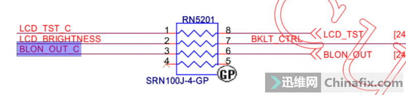
  • 19V must present at sense resistor or high-side mosfet (pin 5-8, drain)
  • 3VALW/5VALW must be present
  • RSMRST# and SLP_S5# must be present before or after power button is pressed
  • Main rail (3V/5V) voltage must be present before or after the power button is pressed
  • SLP Signals must be present

CHECKING 19V RAIL

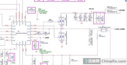
Laptop motherboards incorporate a mechanism to protect itself in the presence of over-voltage or over-current. Over-voltage happens when the maximum voltage threshold acceptable by the motherboard is exceeded.  This value can often be found in the schematic or in the datasheet of the charging IC through the ACDET pin. Over-current happens when any of the filter capacitors and high-side MOSFET in the 19v rail becomes shorted or leaky, charging IC or MAINREG is shorted.

The sense resistor (PR303) is used by the Charging IC(PU301) - BQ735 to detect if current consumption is within normal operating conditions.  19V will not be present if this condition is not met.  This is the reason why sometimes you can measure 19v at the gate of  the two P-Channel MOSFETs (see PQ303 and PQ302).  The charging IC acts as a control switch that turns ON and OFF the 19V supply coming from the ADAPTER. 

Charging Circuit

If this circuit is normal, this charging IC reports its status to SIO via the ACIN pin with the presence of 3.3v.  Other charging circuit implementation requires 0v.
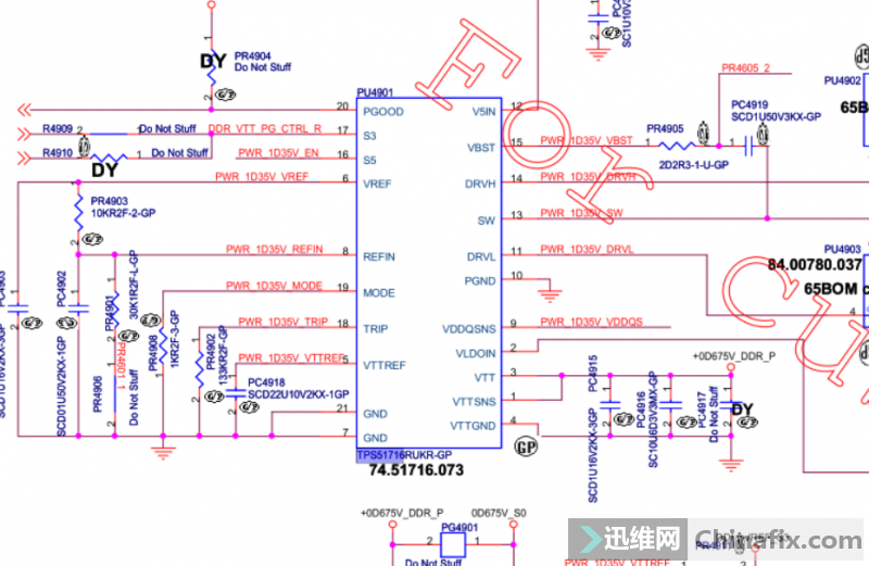
3VALW/3VLP

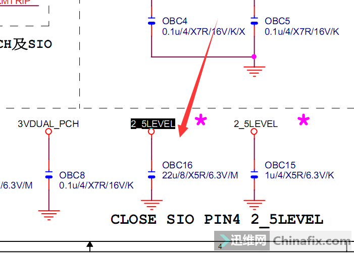
Always on voltage, specifically 3VALW must be present to provide 3.3v supply to SIO (see figure below), PCH, and pull-up voltage for SMB communications between charging IC, SIO and PCH. This supply is always present regardless of the ACPI states the laptop is operating. 

SIO Supply Pins

 The 3.3V supply comes from the LDO output of the MAINREG.  In this case, the 3.3V main regulator is an SY8208B IC or RJ4.

SY8208B

PU401 requires an input voltage of around 4.15V at pin 7 to enable its LDO output 3VLP.  If this is not present, then replace this IC.

RSMRST# AND SLP_S5# MUST BE PRESENT

There are a number of reason why RSMRST# won't come out from SIO. This could be a faulty SIO, corrupted EC firmware, missing 32.768kHz, missing 3.3VALW, busted EC SPI chip, open resistors or PCB traces,  etc.  

In the circuit example, you can measure the ouput through pin 100 of the SIO. 

RSMRST#

It is also possible that the SLP_S5# is missing.  If this is the case, focus on RTC circuit and make sure the RTCVCC, INTRUDER#, RTC_RST#, SRTC_RST#, INTVRMEN have at least 2.3V-3.3V in them.  

SUSB#/SUSC#/SLP_S4#/SLP_S3#

If a power button is pressed, the signal will go through NBSWON# (other names are PWR_SW#, ON/OFFBTN#, etc.) and sent to DNBSWON# going to south bridge chip (PCH integrates both SB and NB).  If everything is normal, SLP_S4#, SLP_S3#  or (SUSC# and SUSB#) will have 3.3v. This signals will trigger SUSON (SUSP#, SUSC_EC#) and MAINON (SUSB_EC#) signals.

If SLP_S4# and SLP_S3# does not come out when the power button is pressed, you may need to reflow, reball or replace the PCH.

If SUSON or MAINON does not come out, then SIO is faulty.

QUICK GUIDE FOR FIXING "BATTERY NOT DETECTED" ISSUE IN ACER ONE 14 Z1402

 We would like to share some ideas for resolving issues in Acer One z1402 where battery cannot be detected by the system. The troubleshooting concept here may be applicable to other laptops with similar charging circuit designs.

SYMPTOMS:

  • Battery is not detected in Windows
  • Charging indicator does not lit

REPAIR NOTES:

  • BAT+ is normal and BAT_SMBCLK and BAT_SMBDAT have pullup voltage of 3.3V.  Also, no activity were noted in the oscilloscope.
  • Found an abnormal voltage reading in battery detector circuit, BAT_V = 0V
  • Pin 3 of Q58 is 0v which means BAT_V is forced to 0v. Expected voltage at this pin should 2.375V for normal operation. (see image)
  • Pin 2 has 3.3V which  should forces pin 6 and pin 5 to 0V. (see image)
  • But actual voltage at pin 5 is 5v which makes it abnormal
  • Further test indicates that D1-S1 junction is open which results in inconsistent reading of 5v in pin 5 and 0v in pin 3.
  • Replacement of Q58 fixed the problem

Battery Voltage Detector

Resolving cases like this can be easily fixed if every component will be checked for normal operation using datasheet or schematic diagram. However, analyzing the circuit and what voltage to expect as you test each pin of the IC is a difficult challenge. 

ACER V5-473 DAZRQMB18F0 W/ MISSING +5V_S5

 Let's suppose you are troubleshooting an Acer V5-473 w/ board code DAZRQMB18F0 and the voltage measurements are as follows: 

This circuit design is found in many laptops and knowing how to troubleshoot them would enhance your capability to fix many laptop problems such as no-power, auto-off and no display problem.

Voltage measurements were done after pressing the power button. Can you analyze the circuit answer the following questions?

  • Based on the above voltage measurements, which component(s) do you think is the potential faulty component? Why?
  • Let's assume that all voltage rails are normal but PR118 is open, what voltage can we measure at +5V_S5? Why?
  • Let's assume that all voltage rails are normal but the drain-source pin of PQ22 is shorted.  What voltage can you measure at +5V_S5?  What will happen?

HOW TO PUT CANON PRINTER IN SERVICE MODE (G2000, G2002, G2100, G2200, G2400, G2500, G2700, G2900)


TEP TO ACCESS SERVICE MODE IN CANON PRINTER

  • Turn off the printer.
  • Press and hold the Stop button.
  • Press and hold the Power button.
  • Release the Stop button (the Power button is still pressed).
  • Press and releasing the Stop button 4 times.
  • Press and hold the Stop button.
  • Release the Power and Stop buttons together.

After both buttons are released, the power indicator will blink green for some time and then the green will light constantly.

If the power indicator did not have constant green light and the printer continue to display an error, it's mean you made a mistake in entering service mode. Turn off the printer and repeat the process.

APPLICABLE PRINTER:

G2000, G2002, G2100, G2200, G2400, G2500, G2700, G2900

Friday, April 5, 2024

How to IDENTIFYING FAULTY TPS51125

TIP 01 - Identifying faulty TPS51125

Tps51125 is commonly used main regulator IC in laptops and macbooks. This guide will help you identify if this IC needs to be replaced.  Use the image as a reference of a normal working 3v/5v main regulator IC.  

TPS51125 chip should have the following voltage readings for normal operations:

  1. Make sure you are getting approximately 19V in VIN
  2. Check if EN0 is present
  3. If EN0 is present, then you must have normal voltages at VREF, VREG3 and VREG5
  4. ENTRIP1 and ENTRIP2 must be within normal voltage range. 
  5. If ENTRIP1 and ENTRIP2 is normal, then you should have 3.3V and 5V at VOUT1 and VOUT 2
  6. PGOOD should have 3.3V indicating a normal operation.

NoteSometimes, ENTRIPx, VOUTx, and PGOOD will only have voltage readings when power button is pressed.

PGOOD:

PGOOD signal is an indicator that the circuit is operating normally.  The absence of 3.3v provides a clear confirmation that there is a problem with this circuit that you need to focus on.  Sometimes, the power button must be pressed before the PGOOD signal becomes present. 

EN0:

EN0 is responsible for turning on VREF, VlaREG3 and VREG5.  If these signals are not present, check EN0 if voltage is normal (see the reference image). Replace tps51125 base on the following conditions:

  • Supply voltage at VIN is present
  • Voltage at EN0 pin is normal
  • Resistance of VREF, VREG3, and VREG5 pins with respect to ground is in the range of kilo ohms or higher
  • Any of the output voltage on VREF, VREG3 and VREG5 pin is missing.

ENTRIP1/ENTRIP2:

Normal voltage for these control signal will turn on the 2-channel output for 3.3V and 5V (V01 and V02). Replace this chip if ENTRIPx has normal voltages but VOx is missing.  Make sure that the load resistance is normal.

 DRVL1/DRVL2:

if any of the load circuit that is connected to VOx is shorted, the TPS51125 will force DRVLx to have 5V to protect the load from over current.  if this is the case, check the load for short, as well as the high-side and low-side MOSFET for leaks.

SUMMARY

In summary, the absence of output voltage at VOx may be caused by missing ENTRIPx signals.  If ENTRIPx signals are present but there is no VOx, then the TPS51125 may need a replacement.

If PGOOD signal is normal but any of the VOx is missing, then you may replace 51125. The absence of PGOOD signal might also indicates a problem with the external circuits feeding input signals (EN0, ENTRIPx) for this chip, or this chip is busted, or any of the load circuit is faulty, including the low-side and high-side MOSFET it drives. Whatever the case, It is a good practice to perform voltage and resistance measurements to isolate and confirm the problem

Sunday, March 31, 2024

ACER NITRO 5 8TH GEN BOARD LA-J871P

 it for DC jack replacement. Check on DC JACK 0 volt.
Found customer’s charger faulty. Connected power supply but there was some continuous noise (tiktik,tiktik)in my power supply. Load 0.01Amp.
Check on DC jack -19V,means DC jack OK.
INPUT COILS,FIRST MOSFET DRAIN =19V, SOURCE =0.1 TO 0.7V FLUCTUATING, GATE VOLTAGE ALSO SAME 0.1 TO 0.7V
CHECK FIRST AND SECOND MOSFET ,BOTH FOUND OK.
REMOVE AC DRIVE RESISTOR AND CHECK STILL SAME CONDITION NO AC DRIVE GENERATING.REPLACE RESISTORS STILL SAME
CHARGING IC VCC =19V, REGN =5.95V ,ACDET= 2.5V OK.,BUT ACOK=0V
CHANGE BOTH VOLTAGE DIVIDER RESITOR FOR ACOK,STILL OV ,SAME CONDITION,
ASK FOR HELP ,RENUKA INFOTECH ASKED ME ABOUT CASE AND SUGGESTED TO CHANGE CHARGING IC
CHARGING IC CHANGED AND CASE SOLVED
THANK YOU VERY MUCH RENUKA INFOTECH SIR &
THANK YOU VERY MUCH SUBODH SIR FOR TEACHING US SO NICELY IN DEPTH AND DETAILS.

Friday, February 16, 2024

How to add an App to Start up in Windows 10

Add apps to startup in Windows 10.

  1. You must create a shortcut of the app that you would like to add to start up. Drag and drop the app from the Start Menu to the desktop the shortcut of that app will be created on the desktop.

    Creating a Desktop shortcut
    Figure 1: Creating a Desktop shortcut

    Desktop Shortcut
    Figure 2: Desktop Shortcut

  2. Open Run command box by pressing the Windows logo + R keys. In the Run command field, type shell: Startup and then press Enter key to open Startup folder.

    Run Command Box
    Figure 3: Run Command Box

  3. Copy and paste the app shortcut from the desktop to this Startup folder and the app is added to startup.

    Startup Folder
    Figure 4: Startup Folder

Monday, January 15, 2024

Touchpad not working on Ubuntu 20.04 and 21.04 - Lenovo Ideapad 5 ,ideapad 3 laptop fix

Open Termninal and follow steps.

sudo su

apt update

apt autoremove

apt upgrade

apt upgrade

apt install build-essentials -y

nano /etc/default/grub

(Edit “GRUB_CMDLINE_LINUX_DEFAULT to GRUB_CMDLINE_LINUX_DEFAULT= “quiet i8042.nopnp=1 pci=nocrs”)

update-grub

apt install git

git clone https://github.com/pavlepiramida/elan_i2c_dkms.git

apt install make dkms

cd elan_i2c_dkms

dkms install 

reboot