Digital multimeters can be used to measure DC and AC voltages, DC and AC currents, resistors, capacitors, frequencies, batteries, diodes, and more. Do you know the correct use of the multimeter and precautions?
How to use the digital multimeter and precautions
First, precautions before operation
(1) Turn the ON-OFF switch to the ON position, check the 9V battery, if the battery voltage is not enough,

Or “BAT” will be displayed on the display. In this case, the battery should be replaced; if it does not appear, follow the steps below;
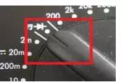
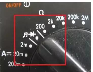
(2) Before the test, the function switch should be placed on the required range, and pay attention to the position of the pointer. As shown below;
How to use the digital multimeter and precautions
(3) At the same time, it is important to note that during the measurement process, if you need to shift gears or change the position of the pins, you must remove the two test leads from the measuring object, and then shift and change the pin position.
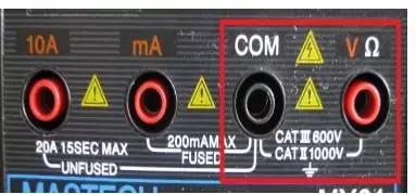
Second, the use of voltage files and precautions When
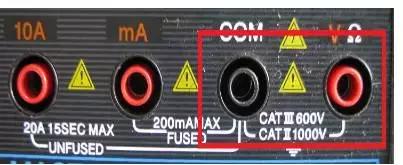
measuring voltage, you must insert the black pen into the COM hole, the red pen inserted in the V hole, as shown in the red box below;
How to use the digital multimeter and precautions
If the DC voltage is measured, the pointer will be turned to the DC position as shown below.
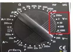
How to use the digital multimeter and precautions
If the AC voltage is measured, turn the pointer to the AC voltage position as shown below.
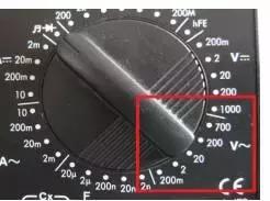
How to use the digital multimeter and precautions
(1) If you do not know the voltage range to be measured, set the function switch to a large range and slowly decrease the range (you cannot change the range during measurement).
(2) If “1” is displayed, indicating overrange, the function switch should be placed in a higher range.
(3) △! means that you should not input a voltage higher than the one required by the multimeter. It is possible to display a higher voltage value, but there is a danger of damaging the internal wiring.
(4) When measuring high voltage, special care should be taken to avoid electric shock.
(5) The internal resistance of the digital meter voltage file is very large, at least in the mega-ohm level, and has little effect on the circuit under test. However, the extremely high output impedance makes it susceptible to induced voltage, and the data measured in some cases where electromagnetic interference is relatively strong may be virtual. Be aware of the effects of avoiding external magnetic fields on the multimeter (for example, when a high-powered electrical device is in use).
(6) In the process of using the multimeter, the metal part of the test pen cannot be touched by hand, so that the measurement can be ensured on the one hand, and the personal safety can be ensured on the other hand.
Third, the capacitance file measurement and precautions
Capacitance capacity measurement method
As shown in the box below, the pointer to the capacitance file (F file)
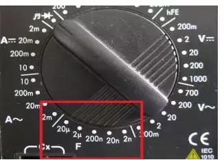
How to use the digital multimeter and precautions
There are two holes on the lower left side of the digital multimeter's gear. The above is written with Cx. The original capacitor to be tested can be measured by inserting it into the inside. If there is a polarity capacitor, pay attention to the positive and negative poles.
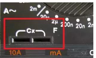
How to use the digital multimeter and precautions
Capacitance refers to the amount of charge stored at a given potential difference; denoted as C, the international unit is Farad (F), which characterizes the physical capacity of the capacitor to accommodate the charge.
1 Farad (F) = 1000 millifarads (mF) = 1000000 microfarads (μF)
1 microfarad (μF) = 1000 nanofarads (nF) = 1,000,000 picofarads (pF)
How to judge the quality of the capacitor?
Use the pointer type multimeter ohm file (the gear position is adjusted with the capacitance), first discharge the capacitor, then the two pens touch the two pins of the capacitor. At this time, the watch pointer will quickly swing and quickly return to the starting position, and then touch again. The pointer will move further and quickly return to its original position. If the pointer swings back to the original position, the capacitor is leaking (the large-capacity electrolytic capacitor has a slight leakage is normal). If the pointer does not move, then the capacitor is broken (the capacity is too small, such as a few PF can not be measured, I can use the 10K file to measure 3N3, 4N7 and other small capacity).
To measure whether the capacitor leaks,
for a capacitor of more than one thousand microfarads, it can be quickly charged with R×10Ω, and the capacity of the capacitor is estimated initially, and then changed to R×1kΩ for a while, then the pointer should not be Return, but should stop at or very close to the place, otherwise there will be leakage. For some timing or oscillating capacitors below tens of microfarads (such as the oscillating capacitor of color TV switching power supply), the leakage characteristics are very high, as long as there is a slight leakage, it can not be used. At this time, after the R×1kΩ gear is charged, Then continue to use R × 10kΩ file to continue measuring, the same hand should stop at the ∞ and should not return.
Fourth, the use of current file and precautions
As shown in the box below, the multimeter current file is divided into AC file and DC file two, when measuring current, the multimeter pointer must be hit to the corresponding gear position to make measurements.
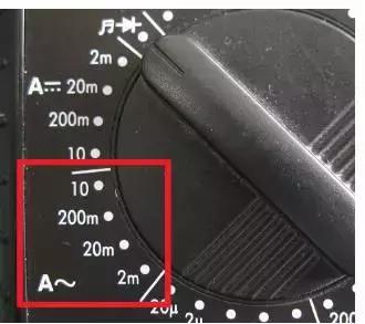
How to use the digital multimeter and precautions
Exchange file
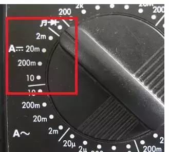
How to use the digital multimeter and precautions
DC file
When measuring current, if using mA file for measurement, insert the multimeter black pen on the COM hole and insert the red test pen into the mA file, as shown in the box below;
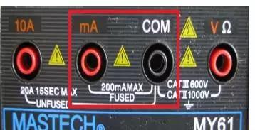
How to use the digital multimeter and precautions
If the measurement is performed using the 10A file, the black test pen remains unchanged and is still inserted in the COM hole, and the red test pen is pulled out and inserted into the 10A hole, as shown in the following figure.
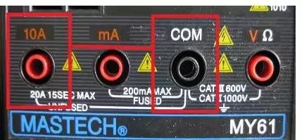
How to use the digital multimeter and precautions
Precautions for current measurement
(1) If you do not know the current range to be measured before use, set the function switch to the maximum range and slowly decrease the range (you cannot change the range during measurement).
(2) If the display only displays "1", indicating overrange, the function switch should be placed at a higher range.
(3) The maximum input current is 10A on the test lead jack. If the measured excessive current will burn the fuse.
V. Application and Precautions of Diode Gears
Move the multimeter pointer to the diode file shown in the box below. The black pen is inserted into the COM hole and the red pen is inserted into the V hole. In addition to measurable diodes, this gear can also be used to measure
triodes , code switches, and whether the lines are connected.
How to use the digital multimeter and precautions
How to use the digital multimeter and precautions
The triode and potentiometer are used to illustrate
the measurement and measurement method of the
triode. The basic structure of the triode is two reverse-connected PN junctions, which can also be simply regarded as the connection of two diodes, as shown in the following figure. There are two combinations of PNP and NPN.
The three successive endpoints are called emitter (E), base (B), and collector (C).
Triode measurement measurement method
Adjust the multimeter to the diode position. This file shows the voltage drop across the diode under test. When judging the type and polarity of the triode. Connect the test leads to any two legs of the triode. If the value is around 700 (millivolts), it means a silicon triode. If the displayed value is around 200, it is a triode. If it is not displayed (open state display 1), you need to exchange the red and black test leads. In addition, the type of the triode can be judged: the red pen is connected to one leg (base), and the other two legs are respectively connected to the black pen (display value), indicating that it is an NPN type triode. If the black pen is connected to one foot (base), the other two legs are connected to the red pen (the value is displayed), indicating that it is a PNP type triode. As for the judgment of the emitter and the collector, other methods are used.
At the same time, through the resistance file, according to the amplification factor of the triode and the internal resistance, it can also be judged whether the triode is of the NPN type or the PNP type.
Judging whether the triode is good or bad
. Connect the test leads to any two legs of the triode. If it is not displayed (open circuit status display 1) or the buzzer sounds, change the red and black test leads and test again. The result is the same, then it can be concluded that the triode is bad.
Sixth, the use of the resistance file and precautions
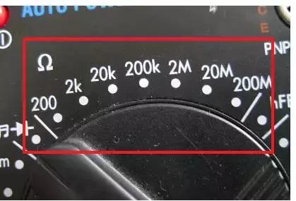
Move the multimeter pointer to the resistance file shown in the box below, the black pen is inserted in the COM hole, the red pen is inserted in the V hole, and the resistance of the measured resistance is measured.
How to use the digital multimeter and precautions
How to use the digital multimeter and precautions
Resistor Measurement Precautions
(1) If the measured resistance value exceeds the maximum value of the selected range, the overrange "1" will be displayed and a higher range should be selected. For resistors larger than 1 MΩ or higher, it takes a few seconds. The readings are stable and normal for high resistance readings.
(2) When there is no input, such as open circuit, it is displayed as "1".
(3) When checking the internal line impedance, ensure that all power supplies of the line under test are powered off and all capacitors are discharged.
(4) There are about four words when the 200MΩ is short-circuited. It should be subtracted from the reading when measuring. If the l00MΩ resistance is measured, it will be displayed as 101.0, and the fourth word should be subtracted.
(5) The resistance file can be used to roughly detect the quality of the capacitor. The red meter is used to connect the capacitor to the positive pole, and the black meter to the capacitor is negative. The reference power of the multimeter will charge the capacitor through the reference resistor. The normal multimeter will display the charging voltage from a low value. Start slowly increasing until the display overflows. If the overflow "1" is displayed at the beginning of charging, the capacitor is open; if it is always displayed as a fixed resistance or "000", the capacitor is leaking or shorted.
(6) When checking the circuit on/off, the function switch should be turned to the “ ” position instead of the resistance file. As long as no beep is heard during the measurement, the circuit can be judged to be unreachable.
(7) When measuring the small resistance value, the two test leads should be short-circuited first, and the self-resistance of the test leads (usually 0. 2 to 0. 3 ohms) should be read to correct the measured resistance.
(8) The resistance file has an overvoltage protection function, and the voltage within the specified range is instantaneously misdetected without causing damage. For example, the maximum allowable input voltage (DC or AC peak) of the DT-830 digital multimeter resistor is 250 volts, which is the safe value of the meter when the voltage is misused, but not charged (such as battery, human body, etc.) Measuring the resistance will cause the accuracy of the multimeter to drop or even break.
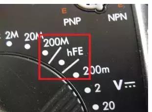
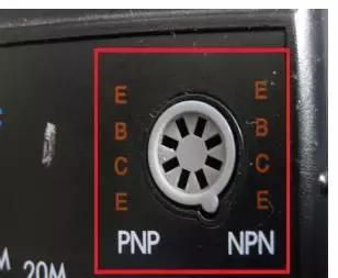
VII. Application and precautions of hFE file
This gear is mainly used to measure the amplification factor β value of the triode. Before the measurement, it must be determined that the triode is PNP type or NPN type, and the polarity of each pin is determined.
How to use the digital multimeter and precautions
How to use the digital multimeter and precautions
Other precautions for
the use of the multimeter (1) In the process of using the multimeter, the metal part of the test pen cannot be touched by hand, so that the measurement can be ensured on the one hand, and the personal safety can be ensured on the other hand.
(2) When measuring a certain amount of electricity, it is not possible to shift gears while measuring, especially when measuring high voltage or large current. Otherwise, the multimeter will be destroyed. If you need to change gears, you should first disconnect the test leads and then change the gears before measuring.
Digital Multimeter Maintenance Precautions
Digital multimeter is a kind of precision electronic instrument. Do not change the line at will, and pay attention to the following points:
1 Do not use over-range.
2 Do not use the multimeter when the battery is not installed or the back cover is not tightened.
3 The battery and fuse can only be replaced after the test pen is removed from the multimeter and the power is turned off. Battery replacement: Pay attention to the operation of 9V battery. If you need to replace the battery, open the back cover screw and replace it with the same type of battery. When replacing the fuse, please use the same type of fuse.
After the 4th meter is used, the switch should be placed in the “OFF” position. If it is not used for a long time, the battery inside the multimeter should be taken out to prevent the battery from corroding other devices in the watch.