like share & subscribe
like share & subscribe

LAPTOP CHIPLEVEL.CHIPLEVEL MOTHERBOARD,,LED/LCD TV .LED/LCD MONITOR.REPAIR.MEMORY.GRAPHICS.PRINTER.LAPTOP.HARD DISK.REPAIRING TIPS.CIRCUIT EXPLANATION.SERVICE TIPS.WORKING PRINCIPLES.TUTORIALS.SCHEMATIC,BIOS Contact 9633034123
Are you an advanced Windows 10 user who wants access to all your PC's processes? "God mode" can be a great solution. To enable "God Mode" right click on the desktop
> New > Folder. re-name the new folder exactly:
GodMode.{ED7BA470-8E54-465E-825C-99712043E01C}
To easily enter into the "God Mode" window, double-click the folder and enjoy!
A quick registry trick.
[HKEY_LOCAL_MACHINE\SOFTWARE\Microsoft\Windows\CurrentVersion\Explorer]
"HubMode"=dword:00000001
The good news is that Windows 10 Home Edition includes Group Policy feature on default installation but this feature is disabled by default. You just have to enable the feature to bring back gpedit.msc.
Please note that this is not using any third-party software for enabling the group policy. In this method, the Code is using the built-in Windows packages installation for installing gpedit.msc. So this method should be 100% safe and should work in all conditions.
INSTRUCTIONS:-
1. Open Notepad.
2. Copy the below code into Notepad.
@echo off
pushd "%~dp0"
dir /b %SystemRoot%\servicing\Packages\Microsoft-Windows-GroupPolicy-ClientExtensions-Package~3*.mum >List.txt
dir /b %SystemRoot%\servicing\Packages\Microsoft-Windows-GroupPolicy-ClientTools-Package~3*.mum >>List.txt
for /f %%i in ('findstr /i . List.txt 2^>nul') do dism /online /norestart /add-package:"%SystemRoot%\servicing\Packages\%%i"
pause
3. Save this File as anything.bat (while saving, first select the File Type as 'All Files' and then save it as 'anything.bat' i.e. with the .bat extension)
4. Run the .bat file as Administrator and wait for it to complete.
5. After it finishes, Press any key to return to command prompt and exit it.
6. Now, you can open gpedit.msc via Windows+R i.e. Run :)
NOTE: This is only for those who are using Windows 10 Home.
The WinSxS folder at:
C:\Windows\WinSxS
is huge and will continue to get bigger the more updates have been installed on your system. If you're using a build that updates read on. The WinSxS folder contains old versions and system components. This folder also contains files for uninstalled and or disabled Windows components. Component files elsewhere in Windows are links to files contained in the WinSxS folder. The WinSxS folder contains every operating system file, meaning any updates will increase the size of this folder. What this large folder does is allow you to uninstall updates which can be useful in the case of a bad update, however this feature is sparingly used. First visit the folder:
C:\Windows\WinSxS
If you're using Windows 10 and your folder is clean it should be around 7 gig. Programs like Windows 10 Manager and AusLogics BoostSpeed will clean this folder for you but there are others. Windows Disk Cleanup will do a average job but the easiest way to do it by yourself is in command prompt. To clean the folder it's a good idea to backup your system but it's not required. Note the size of the folder first, then open up an admin command prompt. Copy and paste the following command:
Dism.exe /online /Cleanup-Image /StartComponentCleanup
(hit enter of course)
After the above command runs use this next command (Note: be patient a large folder take time to clean!)
Dism.exe /online /Cleanup-Image /StartComponentCleanup /ResetBase
And then finally the third and final command
Dism.exe /online /Cleanup-Image /SPSuperseded
Note the size of the folder again and see how much space you saved
1.Download Rufus
2.Run Rufus utility, Its portable and hence doesn’t require an installation.
3.Connect your USB flash drive if you have not already.
DEAD MOTHERBOARD
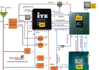
No led indicator at all, no fan moving ,no power .This motherboard require an adapter voltage (12V_15V_16V_18.5V_19V_20V) also 3V and 5V to completely VALW power supply.
without this ADP+ impossible motherboard to a life.
Start by checking dc jack to ensure adapter continuity supply P channel mosfet transistor(adp fet's) end to P channel mosfet transistor for battery fet. This line power is called Main circuit line of VALW power supply. Open schematic (ensure the motherboard model corresponds to and schema).From charger IC page, start your tracing from DC jack to adp P channel mosfet make sure there is continuity from adaptor supply to charger IC.
The most common problem in this section is usually a short circuit or P channel transistor damage. This may cause over voltage protection while Charger IC may detect too high voltage on AC_IN(Adaptor current in detector) . If Charger IC detects high ACIN pin Charger IC will cut of the power by pushing analog to ground on Adaptor current input positive pin to block Adaptor Voltage trough VALW resistive filter.
VALW SHORTED
This may cause adapter led light Blinking or drop ,voltage drop, no current flow(Dead shorted motherboard).
This feed back comes from VALW main power supply line. Check this on schematic by opening Charger IC page and trace any sorted component on VIN and VBAT+ section. Find shorted components by checking all component having Cathode and anode (any components having pin connect to the ground).
To find shorted components faster use PSU with Soft voltage regulation ,using this method will make the shorted components become warm and easy to find.
SMPS 3V_5V SYSTEM
Main Voltage coming from VIN (adaptor voltage ) and B+ section when using Battery
DC/DC main supply input power pin call Vin and output pin called LDO, produced auxiliary power to enable S_5 and opening SMPS gate to produce 3V and 5V supply to the whole circuit.
Measuring point for this 3V_5V system are on the inductors. Some motherboard using auxiliary power 3V and 5V which comes after pressing power switch. Some architecture has 3V and 5V already present before pressing power switch.
To ensure theese voltages are present after presssing power switch, check VSB (Voltage sw_Btn), 3V_EC and 3V Bios chip VCC for 3V. If these voltages are not present, ensure EC firmware is ok first before troubleshooting any circuit failure.Ensure RSMRST# signal is present which is usually 3.3V.
NO DISPLAY FAULT
led indicator on, switch on but no internal or external display.There are 3 boot strap device supported to make motherboard load to display if Bios is hundred percent functional :
1. Processor
Without this motherboard will not display. Power name is VCCORE or CPU Core and enable signal called VR_ON or V_RON as a trigger from Embedded controller (EC) to enable or disable VCCORE IC. Processor need power supply greater than 1.05V but some AMD processor only need power greater than 0.9V.
2.Sodim
Sodim power called VCCRAM. There are 2 power need to make sodim working ,1.5V and 0.75VTT for DDRIII and 1.8V_0,9VTT for DDRII. Get the schematic and find VCCRAM/VTT measuring point to ensure sodim powered well.
3.Bga Chips(SB/NB/VGA)
Chip Power called VCCP. There are very complex power supply system. Chip need 19VALW-5/3VALW-5/3VS-1.2VS-1.05VS.Chip also have their own RAM and need power supply to work Find measuring point on chip by opening chip page on schematic or by checking Voltage rail for specific motherboard.If signal is ok , chip will release PWRGOOD which is 3.3V with tolerance of 10%.
POWER DROP
Led Indicator on ,switching on, Running for few second after that back off.
This symptom happen because of over heat (Thermal Protection), power spike or shortage on VS line.
Processor and Chip are most which can cause power spike, look at VCORE and VCCP circuit line ,circuit has provide stockpile empty pad to add some more capacitor to anticipate power spike during boot up process
Installing mac os to macbook is really not a hard nut to crack as most people presume, mac books are unique laptops with special features which gives the user a high prestige when in use
Reasons for installing mac os x can be as a result of a corrupted os or an os upgrade in order to enjoy much more nice features.
The various versions of mac os are listed as follows: macOS Catalina, mac OS Mojave, mac OS High Sierra, mac OS Sierra, OS X El Capitan download, OS X Yosemite, OS X Mavericks, OS X ,Mountain Lion , OS X Lion
Steps
Download latest and older versions of mac os using the link below
https://support.apple.com/downloads
After downloading the file,it comes in .dmg format, use either rufus or power iso to burn the file into a flash drive by converting the flash to a bootable usb
This feature for the mean time is only available for Windows 10 Insiders, but will be available soon on other windows version. Similarly, wireless file transfers only work on Samsung devices that can run the “Link to Windows” app version 1.5 or higher.
Currently only 100 files can be transferred, each file must be 512MB or less; and both devices must be connected to the same wifi network in order for the process to work perfectly.
When the above requirement are met then you can share files between your PC and Samsung smartphone.
Procedure
Make sure your smartphone and PC are connected to the same wireless network, then follow these instructions to pair your devices.
Open the “Link to Windows” app on your phone and make sure the Link to Windows option is turned on.
To send files from your Samsung phone to your PC
Use “My Files” or “Gallery” to find the file(s) on your phone that you want to send.
Long-press a file until a check mark appears, and then select any other files you wish to transfer.
Long-press again, then drag the files to your desired location on your PC.
Wait for the transfers to complete.
Send files from your Windows PC to your Samsung phone
Open the “Your Phone” app on your PC.
Drag and drop the file(s) to the “Your Phone” windows.
Wait for the files to transfer. Note: closing or minimizing “Your Phone” before the files have been copied over will stop the transfer.
Transferred files are sent to your phone’s “Downloads” folder.
These faults can be detected by counting the number of beeps or blinks at different areas of the laptop like battery power LED, Caps lock, Num lock or Ac power adapter LED. All you have to do is to count the number of beeps and detect the fault.
If you find continuous blinking at the battery power LED then there will be the fault in battery. The reason of fault is the AC adapter is attached and the battery is charging, but does not yet have sufficient charge to power the notebook.
One beep or blink at the Caps or Num lock indicates the fault in CPU. The reason for this can be is that CPU is not functioning.
Two beeps or blinks at the Caps or Num lock tells that the there is the fault of BIOS. This can be due to of BIOS corruption.
Three beeps or blinks at the Caps or Num lock shows the fault in memory. The reason for this fault is that module error is not functional.
Four beeps or blinks at the same Caps or Num lock signifies the fault in graphics. This can be caused by non functioning of graphic controller.
Five beeps at Caps or Num lock indicate the fault in the system board. The failure of the general system board cause this.
Six blinks or beeps at Caps or Num lock tells the fault in BIOS due to the BIOS authentication failure.
If you are encountering with continuous beeps or blinking in Ac power adapter LED than there will be fault in the power adapter. This can be due to the insufficient power supply.
When caps lock and num lock blinks simultaneously, means Pch chip is faulty.